
Description
PRODUCT DISCONTINUED FOR SMALL QUANTITITY ORDERS. CONTACT US FOR POTENTIAL LARGE VOLUME (>25 boards) ORDERS.
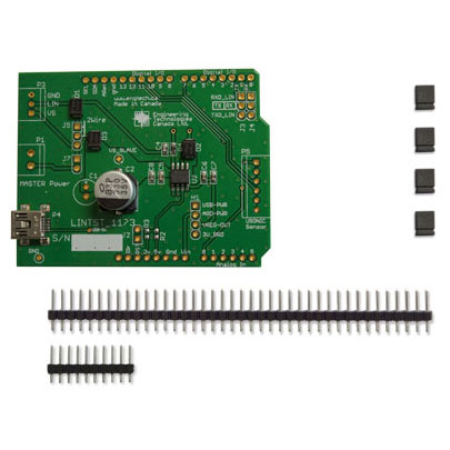
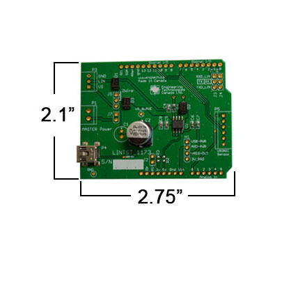
This shield KIT will give your Arduino, Freescale Freedom or Cypress PSoC4 the hardware interface ability to communicate with other devices on a LIN bus. It makes use of the Atmel ATA6623C LIN IC and includes jumper options for one to act as a power-master and supply power to additional connected units downstream. In addition to the standard 3 wire connection, this shield can also be used in low-cost sensor networks and is able to support a special 2-wire connection. This mode is described in detail in the Atmel App note “Two-Wire LIN networking with Atmel“. The App Note describes how power is supplied on the positive signal when not transmitting. Our board includes a large 270uF capacitor to keep the power stable. This also allows your project to be powered over the LIN bus itself.
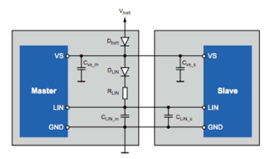
Figure 1. Block circuit diagram for standard 3-wire LIN configuration.
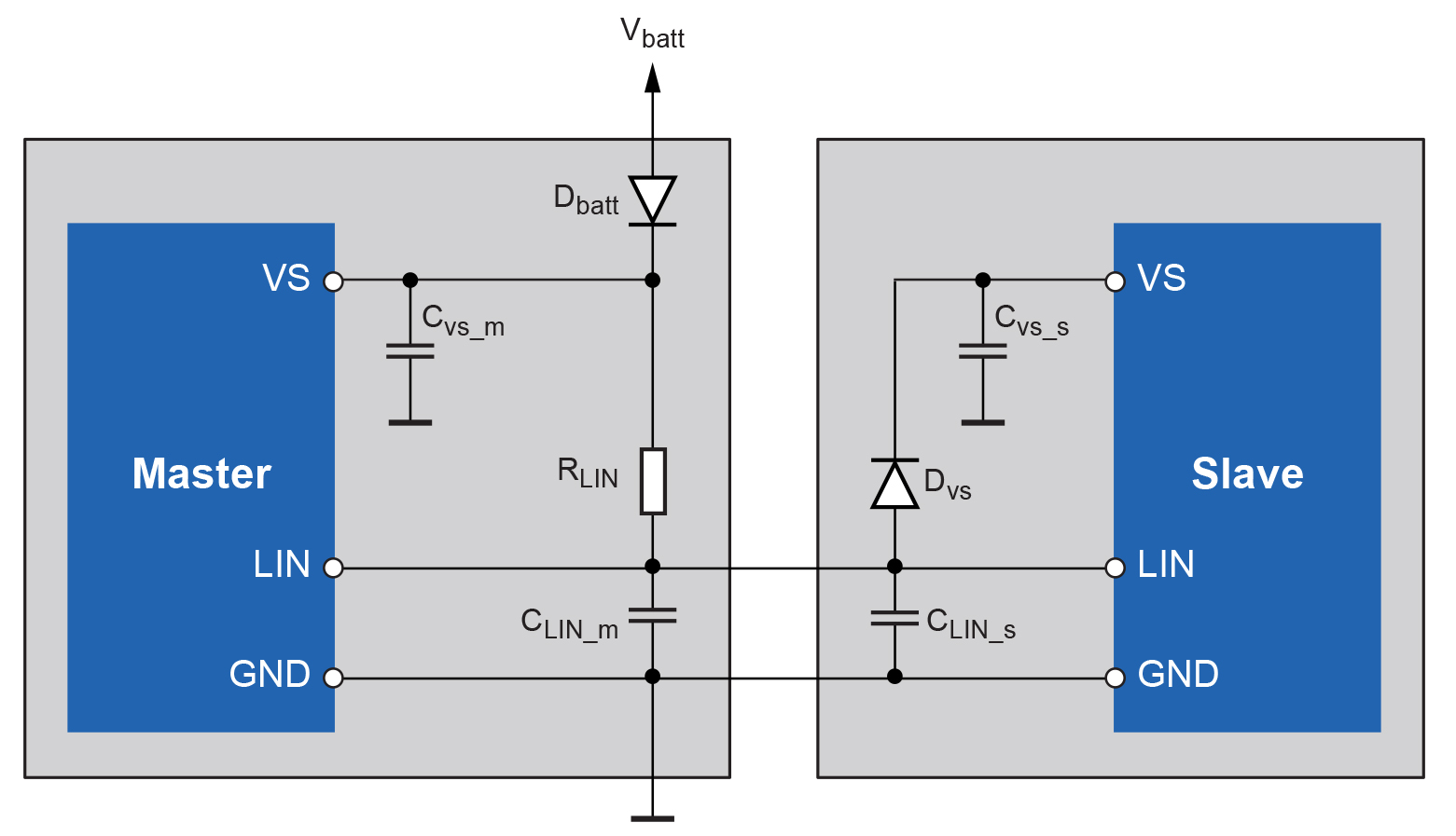
Figure 2. Block circuit diagram for special 2-wire LIN configuration.
Other Features:
- Separate 5 pin connector (not included) can be wired to UART and power of Arduino
- Power can be sourced from Arduino, the LIN chip regulator, separate USB power input
- Through hole pins for optional Super cap (not included)
- RX and TX of UART can be swapped for compatibility with special microprocessor boards.
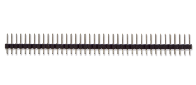
- Note – through hole connectors are included, but not soldered in place.
Schematics and Connection guide for Arduino with jumper descriptions.
Software, libraries, sample code:
At this time we are not able to provide any libraries or starter code. However, schematics are provided for software development. A link is provided below to some example LIN code on Github.
External Third Party Links:
Description of the LIN bus: http://en.wikipedia.org/wiki/Local_Interconnect_Network
Atmel ATA6623C Datasheet: http://www.atmel.com/Images/Atmel-4957-LIN-Networking-ATA6623C-ATA6625C_Datasheet.pdf
Two-Wire LIN networking with Atmel: http://atmelcorporation.wordpress.com/2013/09/06/two-wire-lin-networking-with-atmel-part-1/
Example LIN code on GitHub: https://github.com/gandrewstone/LIN
Disclaimer: Dynamic Monitors has not tried or tested this code, however, we believe it is likely that it will work since LIN on Arduino is just a serial port conversion.
Discussion about voltage:
The Atmel ATA6623 will take an input supply voltage up to 40V.
See the datasheet here:
http://www.atmel.com/Images/Atmel-4957-LIN-Networking-ATA6623C-ATA6625C_Datasheet.pdf
“3.2 Supply Pin (VS) LIN operating voltage is VS = 5V to 27V. An undervoltage detection is implemented to disable transmission if VS falls below 5V, in order to avoid false bus messages. After switching on VS, the IC starts with the fail-safe mode and the voltage regulator is switched on. The supply current in sleep mode is typically 10µA and 57µA in silent mode.”
The LIN bus pin is as follows:
“3.6 Bus Pin (LIN) A low-side driver with internal current limitation and thermal shutdown as well as an internal pull-up resistor according to LIN specification 2.x is implemented. The voltage range is from –27V to +40V. This pin exhibits no reverse current from the LIN bus to VS, even in the event of a GND shift or VBatt disconnection. The LIN receiver thresholds are compatible with the LIN protocol specification. The fall time (from recessive to dominant) and the rise time (from dominant to recessive) are slope controlled.”
Our shield board is configured to provide this supply from either an external power input pin, or in the unique two pin “power scavenging” configuration described by Atmel.
The link to this configuration is given above under “External Third Party Links”
Note: the LOGIC side of this part runs at 3.3V and in addition, there is an internal voltage regulator that supplies up to 85mA of current at 3.3V. Where this power goes can be selected on header H1. We have used it to supply power to the host processor FROM the LIN bus, however, this is not mandatory. Refer to the schematics provided above. By tracing the signals you can choose to jumper H1 or not.


Reviews
There are no reviews yet.